This awesome piece of hardware was claimed to be a punched paper tape reader controller from 1962. I, with no hesitation, picked it up.
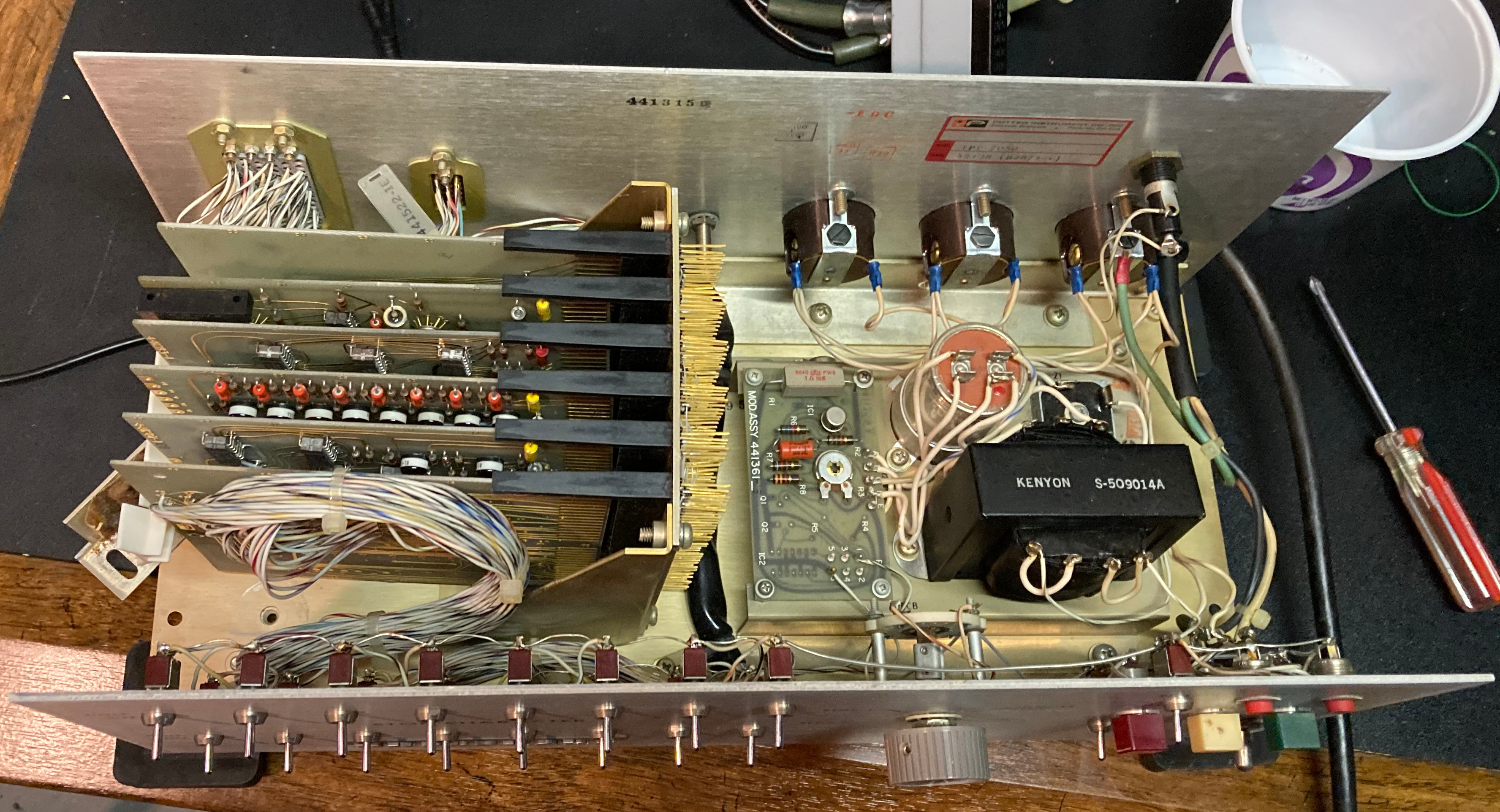
Opening it up confirmed that it was indeed awesome, although the chip date codes put the manufacture date closer to 1970. The right-hand side is taken up by a gigantic transformer and smoothing capacitor. The left-hand side is a group of five logic boards, with a sixth routing the signals from the front panel and connectors to the backplane. The six boards are connected with a big wire-wrapped backplane.
What is it?
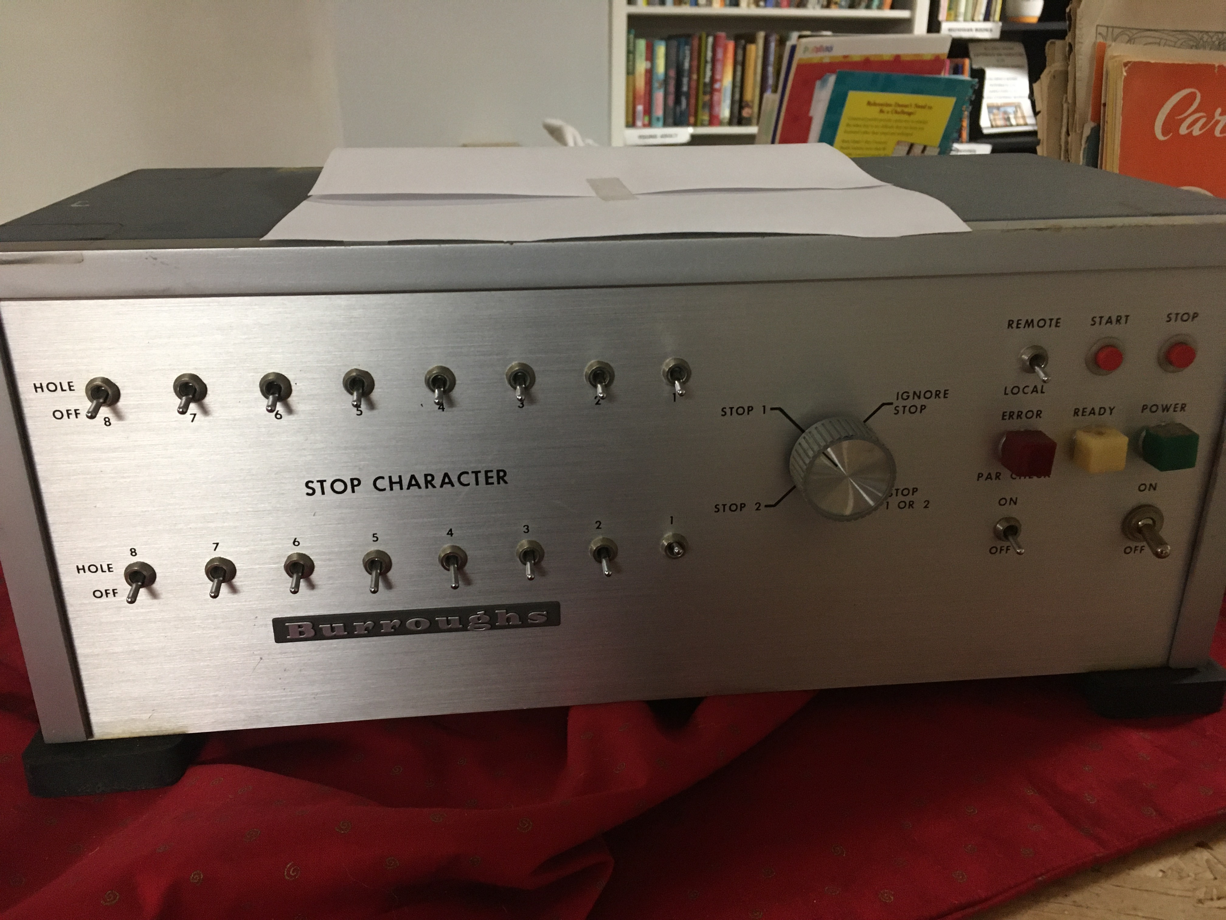
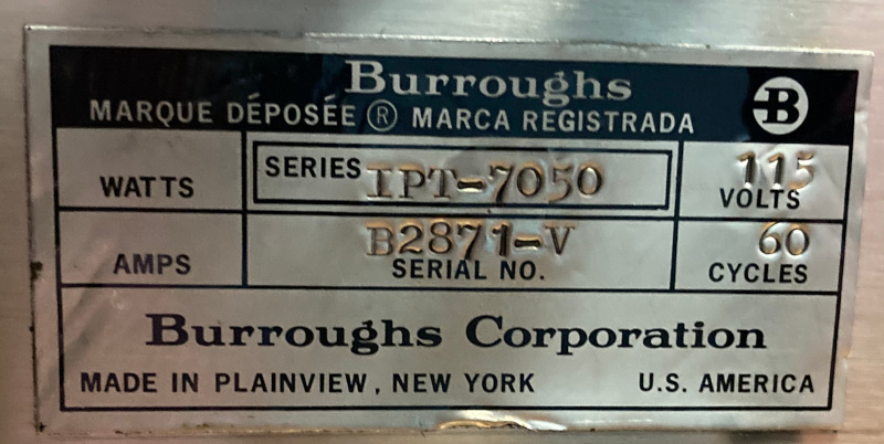
The back of the machine has a nameplate identifying it as a Burroughs IPT-7050. The rest of the case has several other Burroughs logos. However, inside the case, there is a second Potter Instruments nameplate, also identifying it as IPT-7050. The logic boards also have Potter Instruments markings. Searching for these numbers turned up zero results. After searching through scans of old catalogs, I was still unable to find it. The front panel switches to set the stop characters are marked ‘HOLE OFF’, which makes sense for punched tape. After reverse engineering it, a paper tape reader controller is still a likely conclusion.
Reverse Engineering
I started by taking photos of all of the logic boards, then drawing the traces over top in GIMP. For the backplane and interface board, there was no way to see where the identical wires went, so I just tested continuity until I found everything.
The logic is DTµL (Diode-Transistor Micrologic), produced by Fairchild, ITT, and Philco. (The Philco chips are marked 99xx rather than 9xx.) With the exception of one 9601 retriggerable one-shot, all gates are NANDs. The inputs are diodes followed by an inverter. For the four-input gates, each gate has an input without a diode so that it can be extended to almost any number of inputs. Most outputs have only resistors for pullups, so they can be wire-ANDed. The only other integrated circuits are Fairchild µL 914 dual RTL NOR gates in pretty TO-5 with gold leads. They are all used in the same configuration exclusively for one-shots.
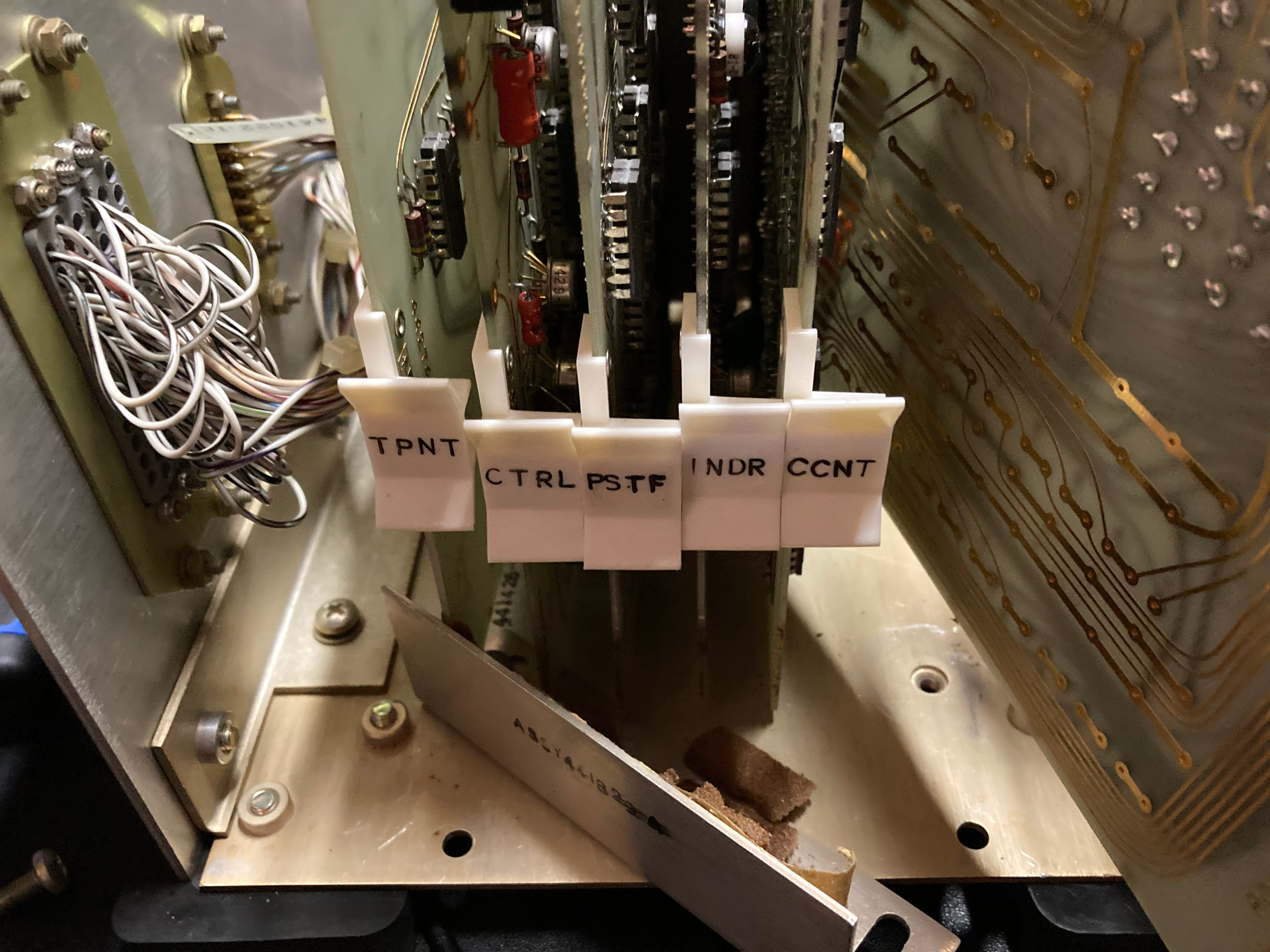
Since it is made of only NANDs, there are fewer clues as to what exactly the circuit is supposed to do. The PSTF board might conventially be represented with XORs for comparing the data to the two stop characters and calculating parity, but it is all implemented with NANDs and inverters. Since I had no idea what was happening while first mapping the board, I ended up drawing all the latches as loops rather than the standard cross over. Once I knew what some of the blocks were doing, I started at the front panel and began labeling nets until I figured out what exactly they did.
What it does
Not much.
It interfaces between the actual tape read head and whatever remote device actually reads the tape data. It has some timing components to indicate to the remote device when there should be a valid data character. It stops the reader when it finds a stop character or a parity error. It also has a ~10ms time limit to reach the next character, so it can stop if the tape breaks or otherwise ends. This also means the reader has to maintain over 100cps as soon as it starts.
Repair
Before powering up the 54-year-old hardware, I disconnected the power supply and tested it first. It conveniently came with an adjustment potentiometer, which I adjusted to get 5V out. This was the first indication of the failure mode of this equipment. During the course of my reversing, I verified that nothing was shorted or obviously broken, so I deemed it safe to power it up. The power light came on and nothing blew up.
At this point, I needed to make it think that it was connected to a tape reader and computer. Each connector must provide power for its own logic signals. The presence of power is also used by the controller to determine if the associated device is connected. The levels are 0V for logic low and something in the range of -10V to -12V for logic high. I saw references to +1/-10V in other similar period devices, so perhaps it is -10V. There is a 9.1V zener diode on the proximity detector for the remote computer, so it has to be at least that much. I used -12V since I had a floating 12V adapter on hand. I used some optocouplers so I could read and control signals from a blue pill. (I knew that drawerful of old quad optocouplers would come in handy!) At that point, I was able to verify that everything was working by connecting the data inputs to -12V. All of the control signals worked as expected. I was able to generate parity errors, timeouts, and a normal stop. The stable signal pulsed. I was able to turn on the ready light and turn it off when I disconnected the drive connector. But some of the data outputs didn’t work. I quickly narrowed down the problem to the output drivers, since the input buffers and all the other logic after them worked fine.
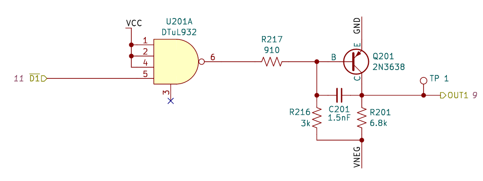
When U201’s output is low, Q201 is on because of R216, making the output also a logic low, or about 0V. When U201 goes high, it pulls the base above ground, and Q201 turns off, which results in a logic high. However, if R217 happens to be much larger than 910Ω, Q201 will never turn off, which means the output will always be low. Unfortunately, this is exactly what happened. Out of the eight 910Ω resistors, only two measured under 1kΩ. I replaced them, and the output drivers all worked. Fifty-year-old carbon resistors can’t exactly be expected to remain within their rated tolerance. A lot of the other resistors were horribly out of tolerance, but for the most part, they don’t affect the operation.
Next
It would be really cool if I could somehow find an original tape reader, but otherwise, I will probably try to build my own. The required 100cps is a bit fast but probably doable. And then maybe I can actually read some punched tape.
But I still want to know what it’s originally from.