Design files and code
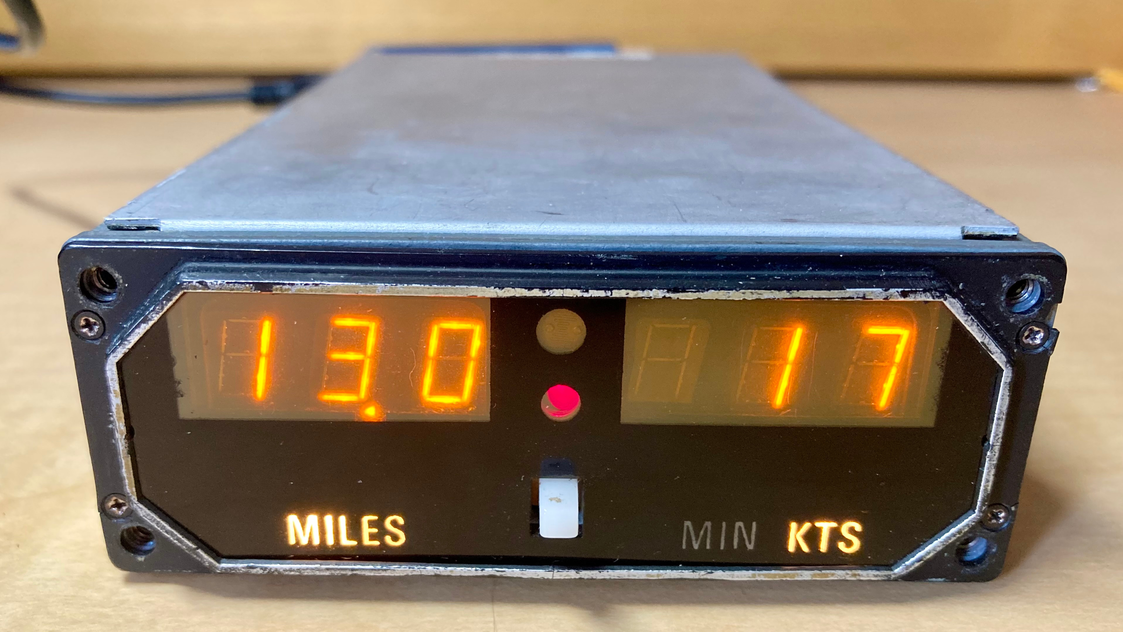
I found this King KI 266 DME Indicator, part of a 1970s DME radio navigation system that would have been mounted in an airplane cockpit. I only have the display part, so unfortunately I won’t be able to use it to navigate, but it does have two awesome gas-discharge seven-segment Panaplex displays. These types of displays operate similar to Nixie tubes (high voltage makes the neon glow), but each cathode is a segment instead of an entire number.
Overall, it was in pretty good shape, but the ribbon cables connecting the two boards were corroded and falling apart. I replaced them with some hookup wire, which was a bit tricky because of the aviation-grade conformal coating.
I powered it up with my best guess from what little I could find online and reversing the PCBs, and it worked on the first try!
(Eventually I found the full manual. My guess was close enough, apparently.)
 A few of the segment drivers are leaky, but fortunately the worst ones are on digits that I didn’t end up using for the clock.
In a cockpit
When it was a DME indicator, the left display would have shown the distance to the ground station, and the switch on the front would have selected ground speed or time to station for the right display. In between the two displays is a rechannel warning LED and a photoresistor for dimming the displays and indicator lights based on the light level. On the right side of the unit are six potentiometers, which calibrate the range for each measurement.
For just showing a few numbers, the case is packed full of electronics. For power, the indicator receives regulated ±15V, used directly for the analog sections, but it also requires 5V for logic and 175V for the display anodes. A few transistors and a King-branded transformer in a metal can form a DC-DC converter to generate the rest of the voltage rails. In bright lights, it draws about 270mA from +15V and 110mA from -15V. The distance and speed are sent by the actual radio part as analog voltages, which the indicator then translates into the numbers to be shown.
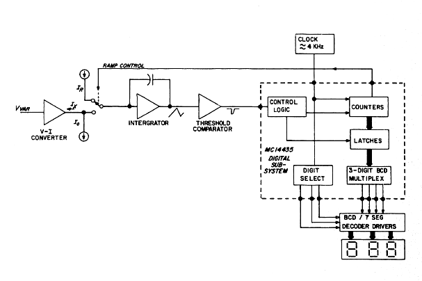 Two semi-integrated dual-slope ADCs convert the analog signal to the displayed numbers. A conversion cycle begins by ramping up the integrator through the input signal for a certain amount of time. After this, the integrator switches to a reference current and ramps down to zero. The time this takes is related to how much the integrator output ramped up and, consequently, how high the input voltage was during the first portion. The integrated digital portion then takes care of timing the ramps and then multiplexing the displays. Although there are only inputs for distance and speed, it can also calculate the time to the station by ramping up with distance and down with speed.
On the bench
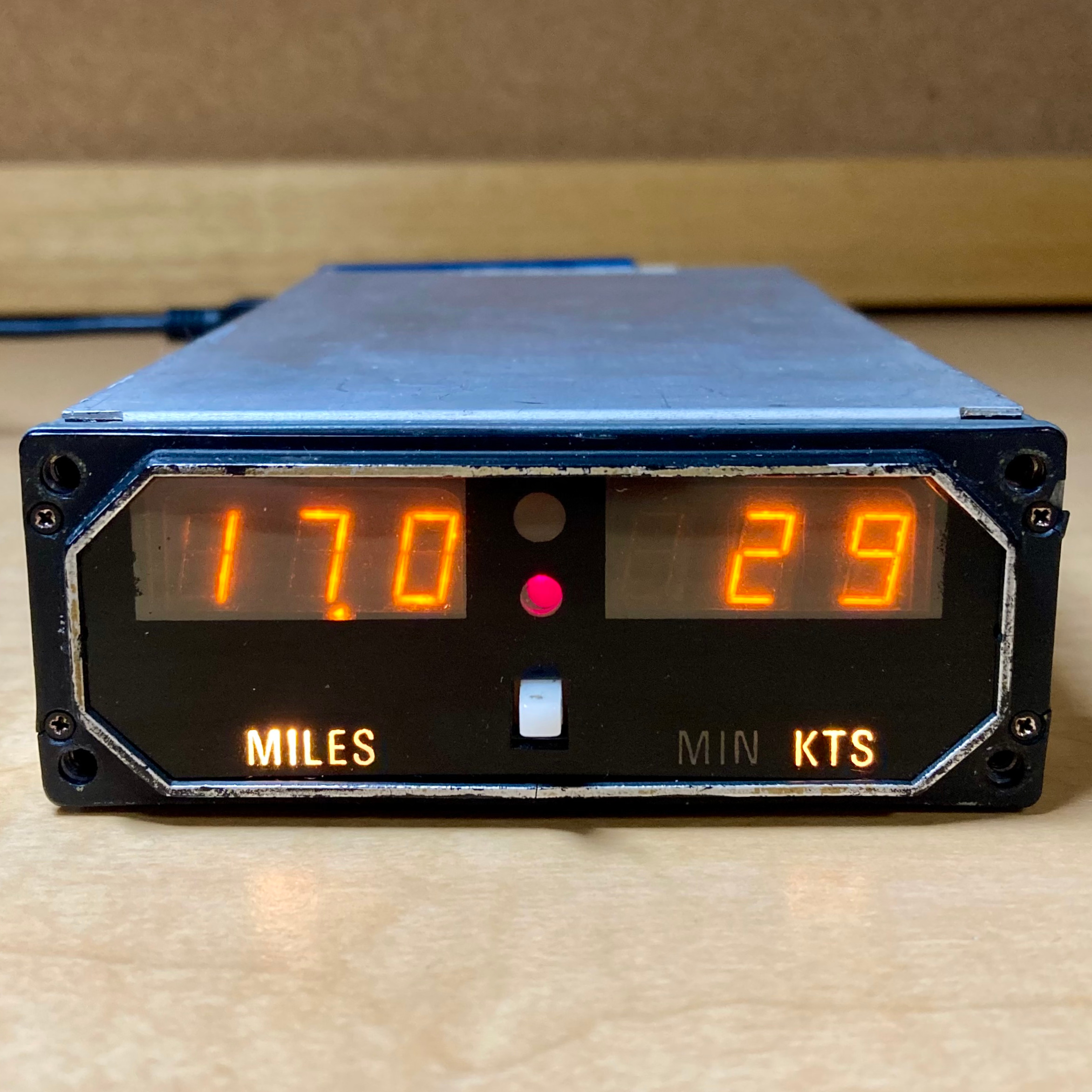
Inspired by the nixie-like displays, I decided to take the obvious path and build a clock. I would turn the DME indicator into a TME indicator, maybe. It’s already in the form of a digital clock—two numeric displays separated by a pair of vertical dots—so I tried to keep the original hardware intact as much as possible. It ended up almost entirely original, except that I had to solder the clock board directly to the connector since I couldn’t find its pair under $30.
The clock backpack is ultra hi-tech in comparison with the internals of the KI 266. Its brain is a PIC16F1454, an 8-bit PIC with USB and the option to run a timer from a separate 32.768kHz crystal. To generate the signals for the indicator, I used the MCP47CVB12, an I²C 10-bit dual DAC. The bandgap reference is enough to display the full range of times, and 10 bits is plenty of resolution to make sure it can show everything accurately. The tricky part was the power supply. I initially considered trying to build a mains power supply, but, in the interest of not electrocuting myself, I ended up with the crazy idea of boosting ±15V from a USB charger. I found the TPS65131, which is a chip with both positive and negative converters that meet the specs to power the indicator.
I designed a PCB in KiCad. Nothing too interesting except for the power supply section, which I knew I wouldn’t get perfect on the first try (I didn’t). I then ordered a set of blue boards from JLCPCB and took a few weeks off.
I hadn’t soldered QFNs before, so assembling the board was a bit of a challenge. I used a syringe to run a line of solder paste along each of the four sides and put a blob on the exposed pad, and then used hot air. I didn’t get enough solder on a few pads, so I went back with a wet iron to touch them up. The big TPS65131 didn’t align itself well, with its gigantic thermal pad. I ended up having to pull it off and do it over again.

The PIC worked on the first try and happily accepted its program. The USB enumeration worked fine, but then it went south. Every time the PIC tried to send something with I²C, it reported a bus collision. Also, when it turned on the output pin to enable the power supply, it would turn itself off every time after about 300us. After lots of rabbit holes and trial and error, I discovered that although the 1454 doesn’t have any analog peripherals, you still have to use ANSEL to switch pins to use digital functions. This solved both problems.
With the PIC and DAC working, I moved to the power supply, which was a horrible pain, as expected. When I first turned it on, the positive output was at the calculated 13.4V, but the negative output hit over -25V without triggering the overvoltage protection. The feedback voltage looked about right, which explained why the protection wasn’t working but not why it was so far off the calculation. After combing the TI forums, I tried removing the feedforward capacitor, which brought it down to a more reasonable -13.9V. Also, I realized that I had connected both feedback dividers right next to their respective switching outputs, which almost certainly affects the feedback accuracy. To try to reduce this, I added a capacitor to ground close to the divider. After hooking the board to the real hardware, I realized that I had neglected to add a switch for the positive voltage input, which puts about 4.5V on the output, causing an awful whine from the transformer in the DC-DC converter in the KI-266. Also, the positive output had trouble starting up, which I traced to it overshooting and triggering and latching the overvoltage protection. After the first problem with the negative output, I decided to try removing the feedforward capacitor on the positive side, and it now starts up almost every time. I may try reducing the output capacitor on the backpack board to reduce the startup current. The power draw depends a lot on the automatic dimming on the DME indicator, varying between about 0.7A and 1.2A (3.5-6W), and significantly more when it is first turned on.
On my desk
After calibrating the voltage ranges to get the correct display using the USB serial port, you can save the settings and then plug it into a normal USB charger. Without a USB connection, the King logo is a button to set the time. And then it’s a functional, if power hungry and somewhat difficult to read, clock!


Helpful stuff
Here’s a great big scanned manual from http://www.mikeg.net for the KN 65, KI 266, and KI 267.
Datasheet for SP-333 display.