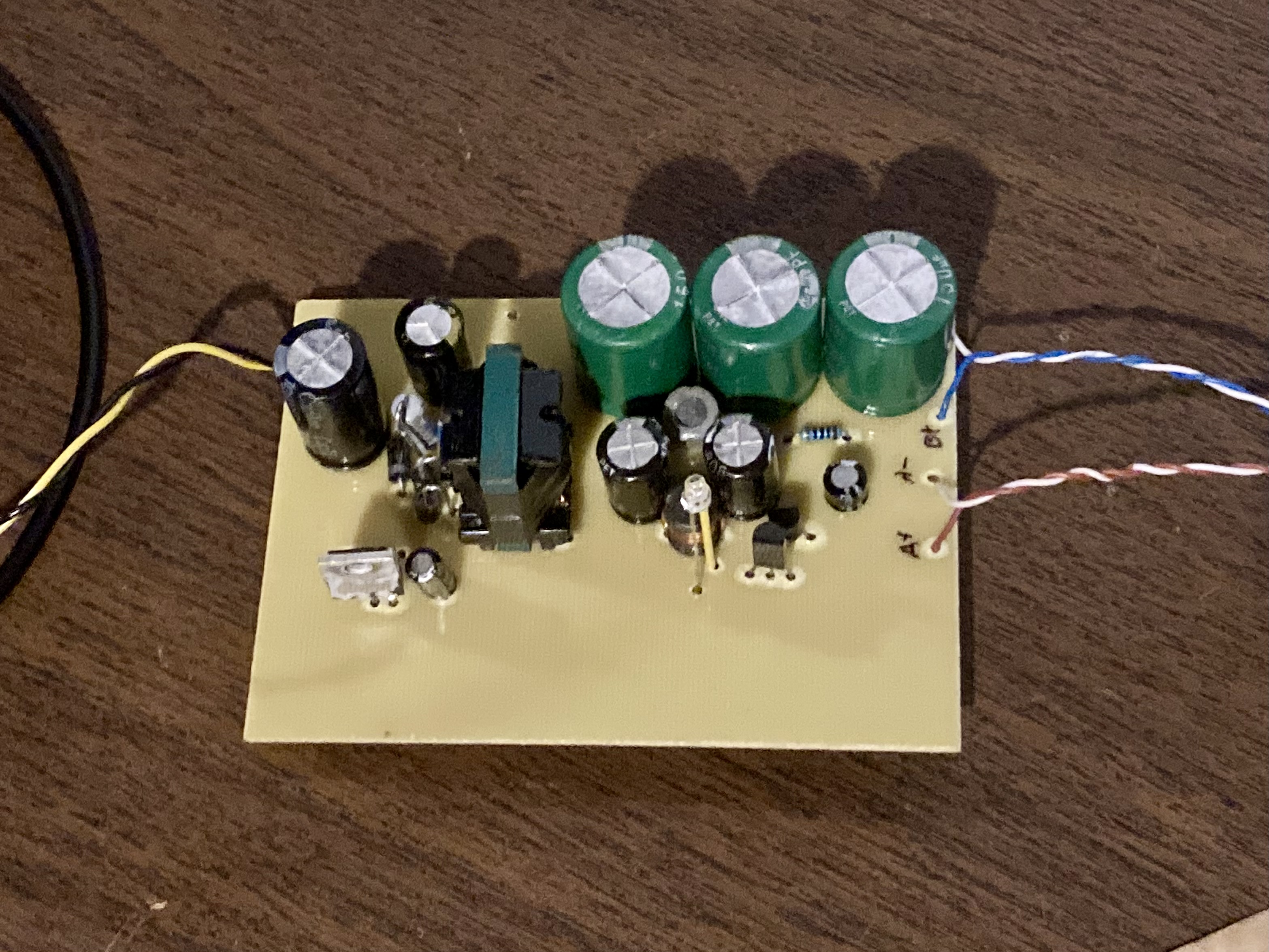
I obtained a battery-powered Silvertone radio from 1941 (model 6353). It was originally powered with a 1.5V cell (about 250mA) to heat the filaments, and a 90V battery (about 11mA) for the anode voltage. To test my radio, I needed a power supply.
I used a flyback converter like Jon Evans’ battery replacement for a similar radio. The high-voltage supply is regulated by the flyback and an LM317 regulates the filament supply from a second output.
Schematic
Input side
The controller (and the RCD primary snubber) came from an off-line power supply, but it still is rated to function down to 18V, so I’m running it with an old 19.5V laptop supply. There is an inrush current limiter so it doesn’t throw sparks while charging the input capacitor. The input capacitor provides charge for switching.
Transformer
I wound the transformer on a flyback core from a burnt-out ATX power supply. I wound turns on the primary until I got a reasonable inductance, then set the others for the correct ratios. With 25 turns on the primary, I wound the 90V secondary with 250 turns (I was hoping to get the controller to start on a lower voltage). The filament secondary and the bias supply are set relative to the 90V output since it is regulated. The filament secondary has 14 turns to get an output a little under 5V, and the bias secondary has 33 turns for about 12V. The transformer is leaky and has lots of capacitance, but it does work.
Feedback
The output voltage is set by D6 and D7 to about 95V. However, with the huge filter capacitors, it takes a while to start up, so D8 and C10 trick the controller into continuing with startup even if it takes a long time (see the TOP247 datasheet).
Output
The filter 90V supply has an LC stage and an RC stage because I figured if one didn’t work well enough both together might. The filament supply has a pi filter and then the LM317 to regulate the output down to about 1.35V.
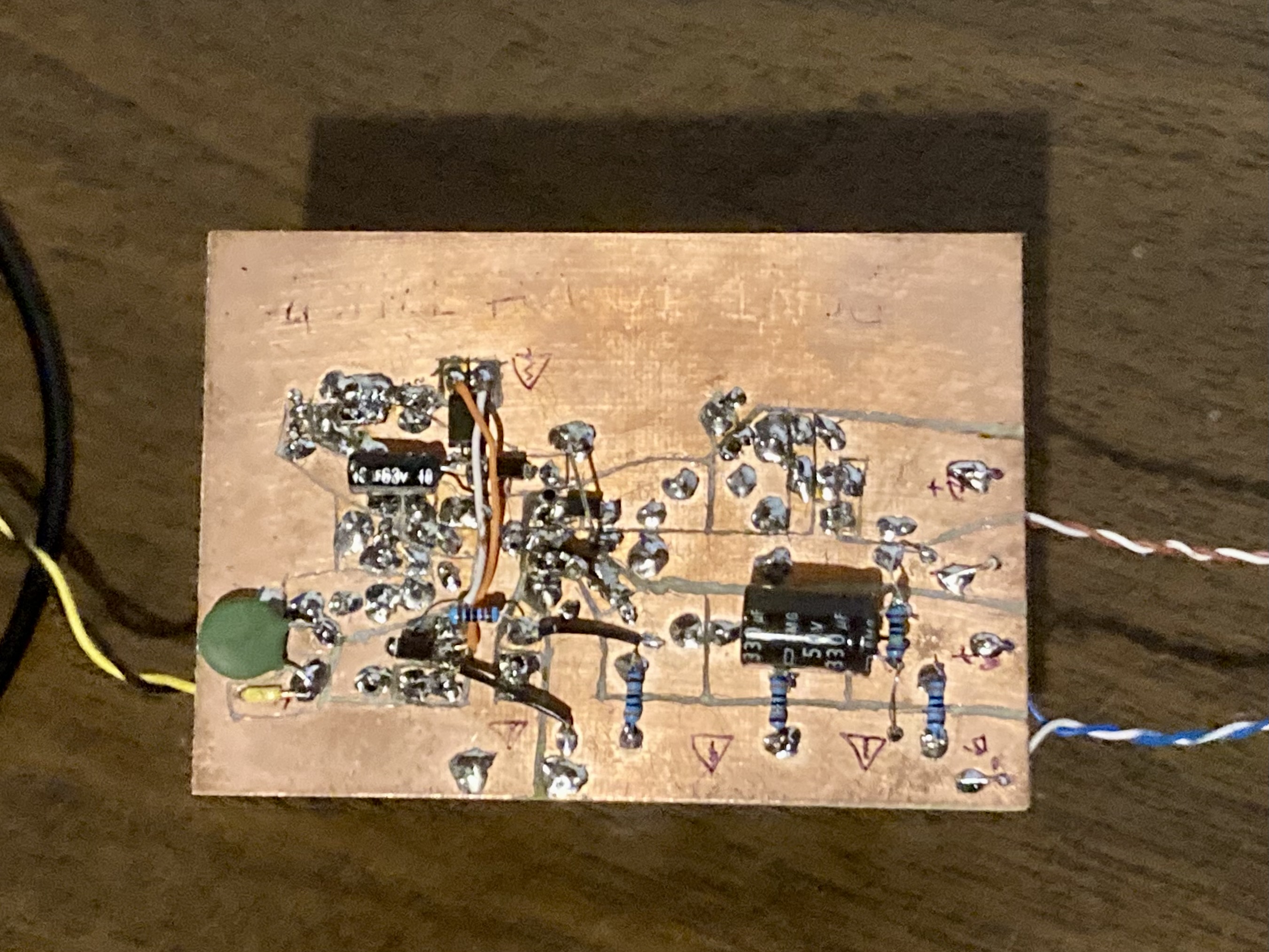
Tracking down noise
With the huge filters on the outputs, both supplies had a ripple of only a couple millivolts, so I was surprised by how much audible noise the radio picked up . . . until I probed between the two supplies and saw almost 2V of ripple! I originally had the two outputs connected to the input ground through small capacitors. I ended up connecting the A- directly to the input ground, since that is the radio chassis ground. The part that really improved the noise was adding capaictors between A- and B-. I also put an film capacitor in the radio. Inside the radio, A- is connected to the ground, and B- is connected through a resistor to ground to control the plate current. This is why the supplies have to be isolated. I ended up using some fancy aluminum polymer capacitors in parallel with some ceramic to get the best performance.
I also spent a lot of time figuring out how to put RC snubbers on the output diodes to damp out the ringing, which helped a little. I put the whole thing in a box lined with aluminum foil shielding, and the end result is a usable radio.