I built a flip-flop using 2N3904 transistors. With the inverting output connected to the input, it toggles accurately with clock frequencies reaching 40MHz. It consumes approximately 25mW.
How ECL works
See next post, where I plan to actually do the math and design something better.
Design and simulation
I copied a bunch of schematics I found on the Internet into LTSpice and then played with the values until it worked. This is what I ended up with:
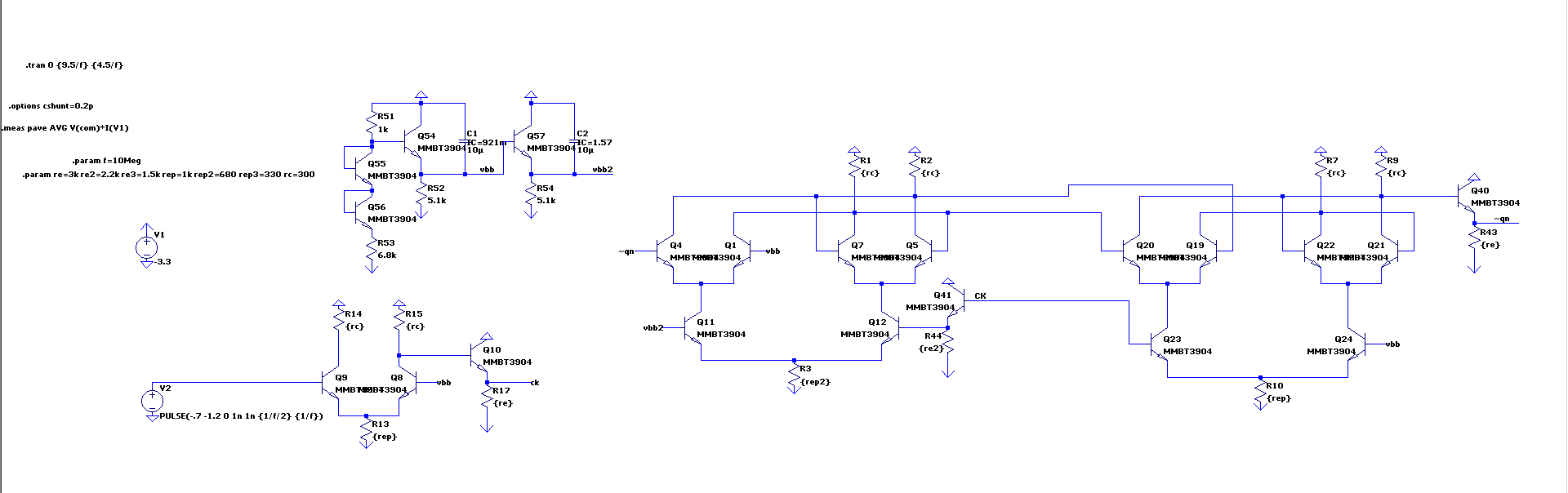
Schematic, MMBT3904 symbol, and MMBT3904 model (from NXP)
The part in the top left generates the threshold voltages. There is a simple buffer for the clock input (so it can be connected to a function generator), and the rest is two latches connected to form a master-slave flip flop.
The Real Thing
I built my flip flop on some copper clad board by cutting out traces with a Dremel and using jumpers where necessary. I used MMBT3904 in SOT-23 and 0603 passives. Here’s how it turned out:
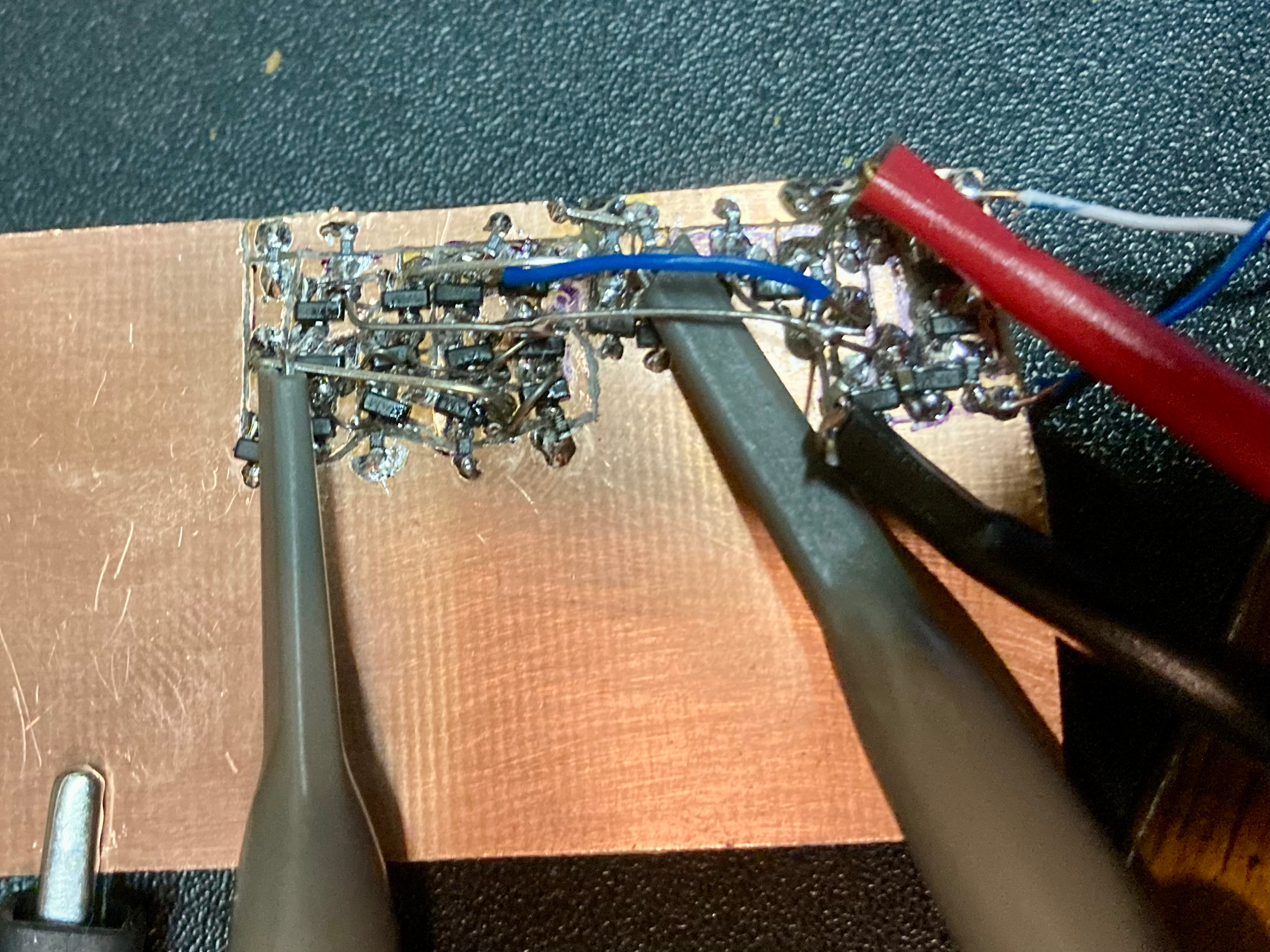
From right to left, the threshold generation, the input buffer, and the flip flop itself.
Verifying the buffer
I first tested the voltage reference and input buffer to make sure they matched
the simulations.
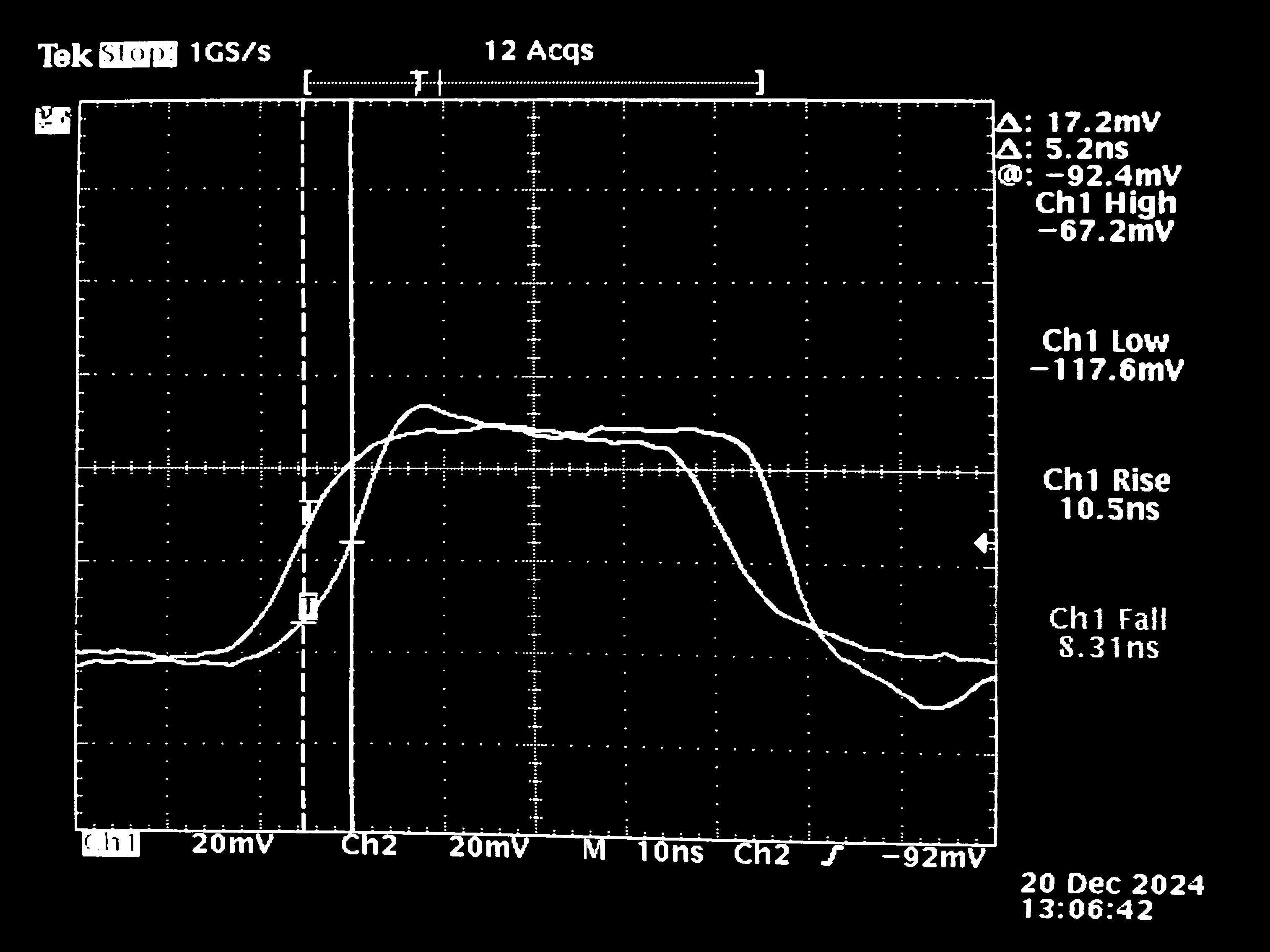 The buffer with a 10MHz input is shown above (voltage scales are off by a factor
of 10 because I used 10x probes without telling the scope). The square wave from
my HP 3325A doesn’t look so square at 10MHz, but the output of the buffer has
faster edges than the input (~10ns), which is good. The propagation delay is around 5ns
on both edges.
The buffer with a 10MHz input is shown above (voltage scales are off by a factor
of 10 because I used 10x probes without telling the scope). The square wave from
my HP 3325A doesn’t look so square at 10MHz, but the output of the buffer has
faster edges than the input (~10ns), which is good. The propagation delay is around 5ns
on both edges.
Verifying the flip flop
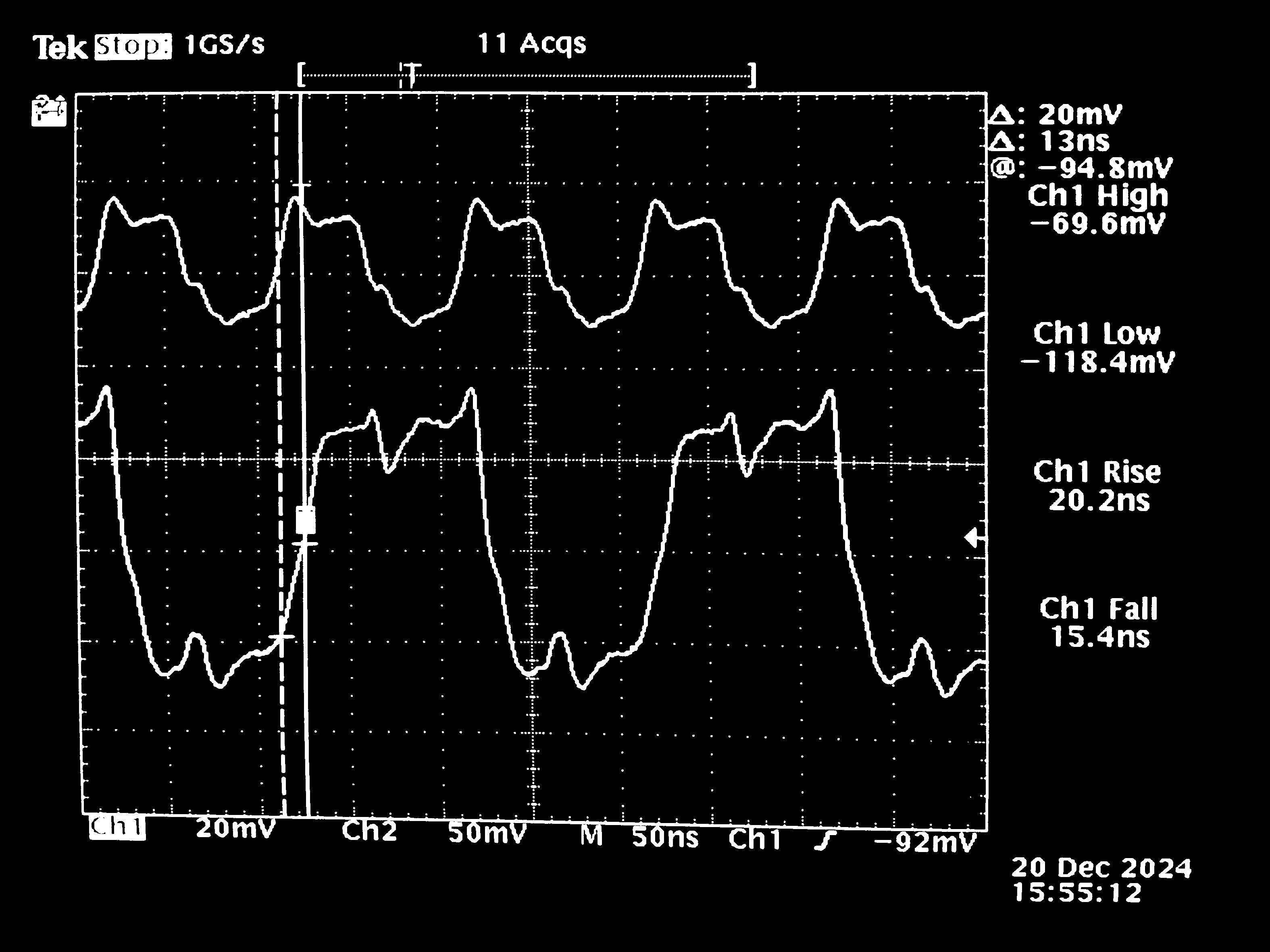 The flip flop worked up to 10MHz square wave, which is the max my function
generator can do. It also worked with a 20MHz sine wave input. I measured about
13ns clock-to-data delay. There is clearly some funny stuff going on with the
bumps introduced on the buffered clock signal and with the way the output starts
to switch on the falling edges of the clock, but it works, and those are also
present, although less pronounced, in the simulation.
The flip flop worked up to 10MHz square wave, which is the max my function
generator can do. It also worked with a 20MHz sine wave input. I measured about
13ns clock-to-data delay. There is clearly some funny stuff going on with the
bumps introduced on the buffered clock signal and with the way the output starts
to switch on the falling edges of the clock, but it works, and those are also
present, although less pronounced, in the simulation.
Pushing the limits
Once I got back to school, I used some fancier equipment to see how high I could
push the frequency. The limit was somewhere between 41-42MHz, although I’m sure
it depends on voltage and temperature and how the transistors are feeling. At
40MHz it seemed pretty solid, although the waveforms start to look more
triangular:
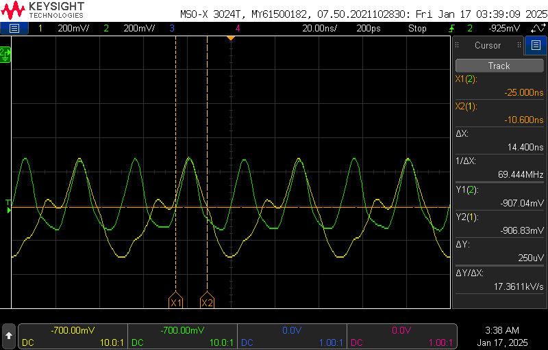 The larger swing on the output versus the buffered clock is clearer here with
the input/output overlaid. While writing this, I discovered that I had used the
same emitter resistors for both latches when building the flip flop. The second
latch has only a single level, which means the voltage across the resistor is
larger, so a larger current flows through the latch, causing a larger output
swing across the collector resistor.
The larger swing on the output versus the buffered clock is clearer here with
the input/output overlaid. While writing this, I discovered that I had used the
same emitter resistors for both latches when building the flip flop. The second
latch has only a single level, which means the voltage across the resistor is
larger, so a larger current flows through the latch, causing a larger output
swing across the collector resistor.